Privacy statement: Your privacy is very important to Us. Our company promises not to disclose your personal information to any external company with out your explicit permission.
With the rapid development of electric vehicles, the concept of V2G has been constantly mentioned. The core idea is to use a large amount of energy storage of electric vehicles as a buffer for the grid and renewable energy. When the load on the grid is too high, the energy storage of electric vehicles will be transferred to the grid. Feeding, and when the grid load is too low, it is used to store the excess power generation of the grid to avoid waste. In this way, electric vehicle users can buy electricity from the grid when the electricity price is low, and get revenue from selling electricity to the grid when the electricity price is high. At the same time, in the face of emergencies such as wars and natural disasters, a large number of electric vehicles can also become emergency power stations, which is of great significance. Some experts have calculated that the maximum load of Beijing in August 2016 is 20.77 million kilowatts. If the output power of electric vehicles is 7 kilowatts, 3 million electric vehicles can achieve citywide power supply.

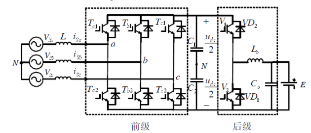
Figure 1 A high-efficiency high power factor charger topology
It consists of a three-phase voltage-type PWM rectifier in the front stage and a current reversible chopper circuit in the back stage. The current reversible chopping DC / DC circuit in the rear stage can be understood as a composite circuit composed of a Boost circuit and a Buck circuit. This circuit can not only realize the forward flow of the circuit, but also realize the reverse flow of current, thereby realizing the entire Two-way flow of charger energy.
Since the non-isolated DC / DC topology is adopted, the high-frequency transformer is removed, the conversion efficiency is improved, and the system cost and loss are reduced, but one situation we have to consider is the leakage of the entire system. As a complex power electronic device, the two-way high-power charger is difficult to avoid leakage problems. It is necessary to limit the leakage current within a certain range through good control strategies at the time of design. Otherwise, whether it is for the power grid or the device itself or life and property Security is risky. At the same time, it is also necessary to adopt a basic protection method to prevent the leakage of electricity when the leakage exceeds the expectation.

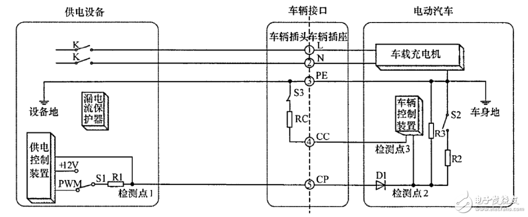
Figure 2 Vehicle-mounted motor input control guide circuit
The above picture is taken from QC / T 895-2011 "Conductive Car Charger for Electric Vehicles" and reflects the general model of the connection between the power grid and the charger. The car charger is powered by the charging cable. The car charger will The connected AC power is converted into DC power to charge the battery. When feeding the power grid, the battery converts the DC power into AC power through the on-board charger and feeds it back to the power grid through the charging cable. A leakage current protector is installed inside the power supply equipment (charging pile) to protect the entire power grid and the energy exchange process of electric vehicles. The leakage current protector is also called a residual current protector (RCD). RCD is that basic protection method, so its reliability is crucial.
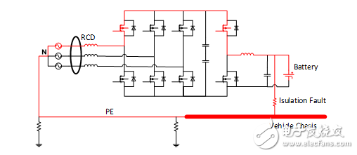
We all know that the power supply system has three-phase three-wire system and three-phase four-wire system. The International Electrotechnical Commission (IEC) stipulates TT system, TN system and IT system. my country basically adopts the TN system, and the connection between electric vehicles and the power grid also adopts this system. When using this two-way high-power charger, the limitations of the DC / DC isolation transformer are lost, and the battery takes the lead in freedom, it is no longer isolated from this system. Therefore, during the long-term use of the battery, if the DC bus has an insulation failure, the leakage will be fed back to the AC side through the body grounding PE wire. Take the battery DC bus positive leakage as an example, the leakage model is shown in the figure below.

Figure 3 Leakage model of battery positive to ground short circuit
It can be seen that the battery DC bus positive leakage is fed back to the AC side to form a loop. This unexpected DC current will affect the entire system. If we simulate the equivalent circuit, we will find that the entire charging current is distorted, resulting in charging efficiency Reduce, or even reduce battery life. A more serious situation is that if the PE wire is disconnected and the ground wire is missing, this part of the current may pass through the human body and cause harm to the human body. If DC current enters the power grid, the consequences are even more unimaginable and will cause harm to the entire distribution network. Therefore, when DC leakage occurs, the circuit must be disconnected to check the device, and the function of detecting leakage and disconnecting the circuit is naturally handed over to the residual current protector (RCD).
According to the requirements of GB / T 18487.1-2015, the residual current protector in the charging pile should be of type B or A. The type A RCD superimposes the power frequency AC residual current, the pulsating DC residual current and the pulsating DC residual current by superimposing 6mA to smooth the DC residual current to ensure tripping; the type B RCD includes the characteristics of the type A, in addition, it can also be used for 1000 Hz and below sinusoidal AC Current, AC residual current superimposed smooth DC residual current, pulsating DC residual current superimposed smooth residual current, pulsating DC residual current generated by two-phase or multi-phase rectifier circuit, smooth DC residual current to ensure tripping. It can be found that when DC leakage occurs, only Type B RCD can protect it.
However, subject to technology and cost, at present, almost all of the leakage protectors in the pile are type A, and it is impossible to protect pure DC leakage. In fact, the leakage component in the V2G system is very complicated. Whether it is an isolated or non-isolated charger, there is a risk of DC leakage. This article focuses on the consideration of the non-isolated charger solution brought by the battery DC leakage hazard.
In the process of implementing electric vehicle V2G, we need to consider how to achieve integration and miniaturization, and at the same time, we must also take into account the various components of the entire system. Observing the current status and future development direction of the electric vehicle field, from the perspective of leakage protection, we urgently need to upgrade the current type A residual current protector to type B, which is a responsible approach for the entire industry.
Magtron's overall SoC chip solution based on iFluxgate technology digitally integrates B-type leakage protection, and provides a cost-effective B-type leakage solution for RCCB's technology upgrade from traditional AC / A-type to B-type. Provide a reliable guarantee for the charging and discharging safety of electric vehicles.
references
[1] Hu Long, Luo An, Liu Yuehua, Xie Longyu, Zhuo Yanping, two-way efficient high power factor electric vehicle charger research
[2] Zhu Yulong, consideration of leakage current model of non-isolated vehicle charger.
[3] GB / T 18487.1-2015 "Electric vehicle conductive charging system Part 1: General requirements"
[4] GB 22794-2008 Type B residual current operated circuit breakers (Type B RCCB and Type B RCBO) without and with overcurrent protection for household and similar purposes
Enviar e-mail para este fornecedor

Privacy statement: Your privacy is very important to Us. Our company promises not to disclose your personal information to any external company with out your explicit permission.

Fill in more information so that we can get in touch with you faster
Privacy statement: Your privacy is very important to Us. Our company promises not to disclose your personal information to any external company with out your explicit permission.